

| 307-01 Automatic Transmission - Vehicles With: 6-Speed Automatic Transmission - 6F35 | 2013 - 2014 Fusion |
| Overhaul | Procedure revision date: 07/15/2013 |


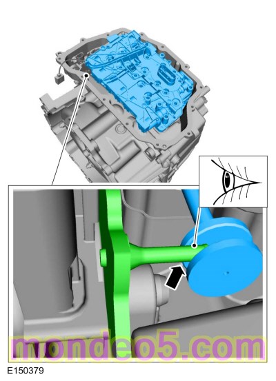
NOTICE: The torque converter is heavy. Be careful not to drop it or damage will result.
Special Tool(s) : 307-091 Handle, Torque Converter
NOTE:

NOTICE: Do not use water-based cleaners or mineral spirits to clean or flush the torque converter or transmission damage will occur. Use only clean transmission fluid designated for the transmission and torque converter being serviced.

NOTE: Note the location of the stud bolts for assembly.


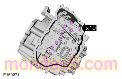
NOTE: Note the location of the short and long main control-to-transmission case bolts for reassembly.


NOTE: Note the location of the stud bolts for assembly.


NOTE: Simultaneously lift the drive, driven sprockets and chain.


NOTE: Note the location of the snap ring gap for assembly.


NOTICE: Do not clean in water or with water-based solvents. Damage to the component may occur.
NOTE: The low One-Way Clutch (OWC) should not be disassembled.
Check for cracks and damaged splines. The internal splined section should rotate clockwise and lock when rotated counterclockwise.


NOTE: If the No. 1 thrust bearing is stuck to the overdrive/direct clutch assembly, remove the No. 1 thrust bearing from the overdrive/direct clutch assembly.


NOTE: Note the location of the snap ring gap for assembly.

NOTE: Note the position of the return spring for assembly.

NOTE: Note the position of the intermediate clutch piston for assembly.
General Equipment : Long Nose Pliers


NOTICE: Do not drive the manual control shaft pin through the manual control shaft. The manual control shaft pin will contact the transmission case causing damage to the transmission case.
Special Tool(s) : 211-061 (T78P-3504-N1) Remover, Roll Pin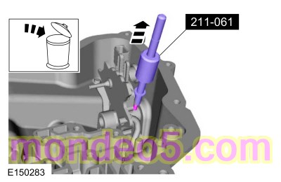
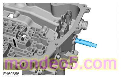


NOTICE: If the LH transmission case bushing or the LH halfshaft bushing surface shows signs of excessive wear or damage, a new LH transmission case bushing and a new LH halfshaft must be installed, or excessive noise or transmission failure can occur.
If the LH transmission case bushing or the LH halfshaft shows signs of excessive wear or damage, install new components.


NOTE: TCC control valve retainer shown assembled in the pump body, main pressure regulator valve retainer similar.

NOTE: The dot on the inner pump gear faces up.


NOTE: Use a new seal.
Material : Motorcraft® MERCON® LV Automatic Transmission Fluid / XT-10-QLVC (WSS-M2C938-A) (MERCON® LV )

NOTICE: The piston return spring, snap ring or snap ring retainer from the low/reverse clutch side of the center support are not interchangeable with the forward clutch side of the center support. When disassembling the center support, be careful not to mix the components from the low/ reverse clutch side with the forward clutch side of the center support. Failure to assemble the center support with the components in the correct side will result in damage to the center support, low/ reverse or forward clutch.
NOTE: The low/reverse clutch piston in the center support is the side of the center support with the long legs.
Position the center support on a press with the long legs facing up.


NOTE: The forward clutch piston in the center support is the side of the center support with the short legs.
Position the center support on a press with the short legs facing up.


NOTE: The forward clutch piston in the center support is the side of the center support with the short legs.
Short leg side of the center support facing up.


NOTICE: The piston return spring, snap ring or snap ring retainer from the low/reverse clutch side of the center support are not interchangeable with the forward clutch side of the center support. When assembling the center support, be careful not to mix the components from the low/ reverse clutch side with the forward clutch side of the center support. Failure to assemble the center support with the components in the correct side will result in damage to the center support, low/reverse or forward clutch.
NOTE: Make sure the snap ring is seated in the groove.
General Equipment : Flat Headed Screw Driver


NOTE: Make sure the snap ring is seated in the groove.
General Equipment : Flat Headed Screw Driver


NOTICE: Only compress the direct clutch piston return spring far enough to take the tension from the direct clutch cylinder off the snap ring. If the piston is compressed too far, the piston alignment tab may be broken off.
Special Tool(s) : 307-584 2-6 Spring Compressor , 307-589 Overdrive clutch and balance piston service set


NOTE: Install the return spring with the flat side facing down.


NOTICE: Only compress the direct clutch piston return spring far enough to take the tension from the direct clutch cylinder off the snap ring. If the piston is compressed too far, the piston alignment tab may be broken off.
Special Tool(s) : 307-584 2-6 Spring Compressor , 307-589 Overdrive clutch and balance piston service set


NOTE: Holes face up on the clutch piston return spring.


NOTICE: Be sure the bleed hole is aligned in the correct position as noted during disassembly or damage to the transmission can occur.

NOTE: Position the clutch piston return spring on the piston to align the piston before pushing it in its bore. The tabs of the return spring should fit into the indentions of the piston and the 2 outer tabs should be at the clockwise most position of the open area at the bottom of the transmission case. The bleed hole on the piston should be aligned between the inner double tabs of the return spring.


NOTICE: Be sure the return spring is positioned correctly with the forward clutch bleed hole aligned between the inner double tabs and the outer tab in the clockwise most position of the slot at the bottom of the case or damage to the transmission can occur.
NOTE: The tabs of the return spring should fit into the indentions of the piston and the 2 outer tabs should be at the clockwise most position of the slot at the bottom of the case. The bleed hole on the piston should be aligned between the inner double tabs of the return spring.

NOTICE: Be sure the snap ring is aligned with the gap facing the front of the transmission or damage to the transmission can occur. The front of the transmission is where the low/reverse and forward (1, 2, 3, 4) clutch hydraulic ports are located.
NOTE: Align the gap of the snap ring to face the front of the transmission.


NOTICE: Be sure the return spring is centered or it can bind on the snap ring groove and cause damage to the transmission case.
Special Tool(s) : 307-574 Forward Clutch Spring Compressor , 307-633 2-6 Piston return spring Comp

NOTICE: Be sure to install the No. 1 thrust bearing with the flat side facing up or damage to the transmission can occur.

NOTICE: Be sure to install the No. 3 thrust bearing with the flat side facing down or damage to the transmission can occur.


NOTE: Position the clutch plates, temporarily reversing the top friction and steel plates for the clutch stackup measurement.


NOTE: When the intermediate (2, 6) clutch is correctly installed, a friction plate is on top.


NOTE: Note the position of the pressure plate. When installing the center support, the long support legs must fit through the pressure plate and rest on the One-Way Clutch (OWC).


NOTE: Position the wave spring and clutch plate, temporarily reversing the wave spring and steel plate for the clutch stack-up measurement.


NOTE: When the low/reverse clutch is correctly installed, the wave spring is on top.

NOTE: Be sure the center support is installed with the long support legs facing down and the feed holes facing the front of the transmission.


NOTICE: Be sure to install the forward (1, 2, 3, 4) clutch beveled snap ring with the flat side facing down or the snap ring can come loose, causing damage to the transmission.
Install the clutch beveled snap ring with the flat side down with the gap facing the front of the transmission.


NOTICE: Make sure to hold the manual control lever while tightening the manual control lever nut or damage to the manual control lever and park components will occur.
Torque : 24 Nm
NOTE: Simultaneously lower the drive, driven sprockets and chain.
Lightly tap on the driven sprocket to be sure it is fully seated in the case.


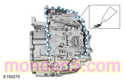
NOTE: Be sure the sealing surfaces of the torque converter housing and the transmission housing are free of oil before applying silicone.
Material : Ultra Silicone Sealant / TA-29
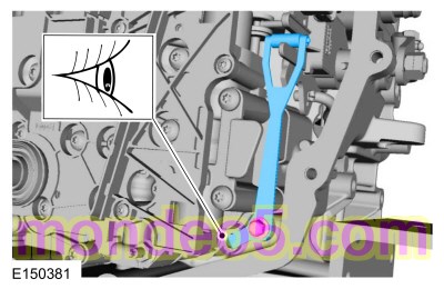
NOTE: Be sure the torque converter housing stud bolt is in the correct location as noted during disassembly.
Torque : 24 Nm
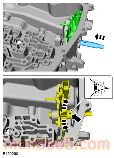
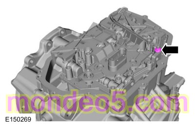
NOTE: Be sure that the manual pin (part of the TR sensor) is correctly installed in the manual valve.

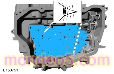
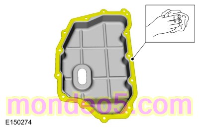
NOTE: Be sure the main control-to-cover seal is installed with the holes facing up.

NOTE: Install the main control cover stud bolts in the correct location as noted during disassembly.
Torque : 12 NmNOTICE: The torque converter is heavy. Be careful not to drop it or damage will result.
Special Tool(s) : 307-091 Handle, Torque Converter

Copyright © Ford Motor Company