
| 502-00 Uni-Body, Subframe and Mounting System | 2013 - 2014 Fusion |
| Removal and Installation | Procedure revision date: 04/22/2013 |
Removal
NOTICE: Suspension fasteners are critical parts that affect the performance of vital components and systems. Failure of these fasteners may result in major service expense. Use the same or equivalent parts if replacement is necessary. Do not use a replacement part of lesser quality or substitute design. Tighten fasteners as specified.
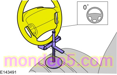
NOTICE: Disconnect the battery ground cable anytime the steering gear is being serviced or damage to the steering gear internal power relay may occur resulting in steering gear replacement.
Refer to: Battery Disconnect and Connect (414-01 Battery, Mounting and Cables, General Procedures). WARNING:
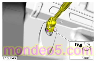
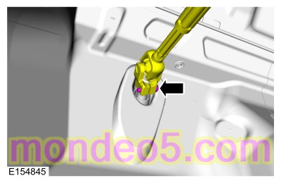
Do not reuse steering column shaft bolts. This may result in fastener failure and steering column shaft detachment or loss
of steering control. Failure to follow this instruction may result in serious injury to vehicle occupant(s).
WARNING:
Do not reuse steering column shaft bolts. This may result in fastener failure and steering column shaft detachment or loss
of steering control. Failure to follow this instruction may result in serious injury to vehicle occupant(s).
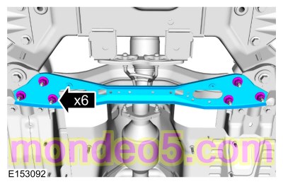
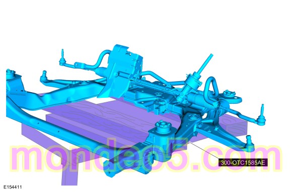
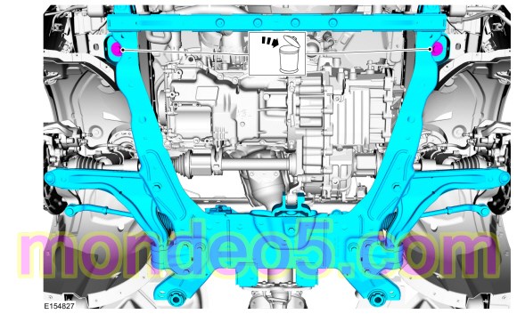
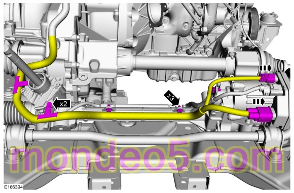
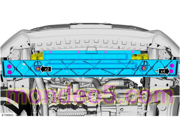
NOTE: Index-mark the subframe for reference during installation.
Marker. On both sides.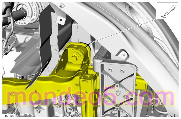
NOTE: Index-mark the subframe for reference during installation.
Marker. On both sides.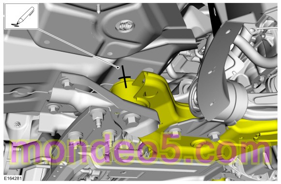
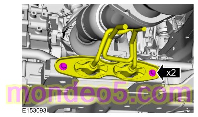
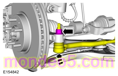
NOTICE: Do not use a hammer to separate the outer tie-rod end from the wheel knuckle or damage to the wheel knuckle may result.
NOTICE: Use care when installing the tie rod separator or damage to the outer tie-rod end boot may occur.
On both sides. Discard the specified component. Follow local disposal regulations.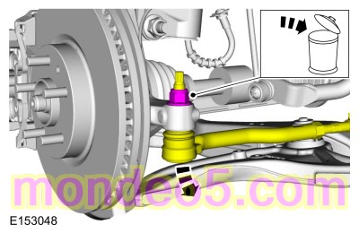
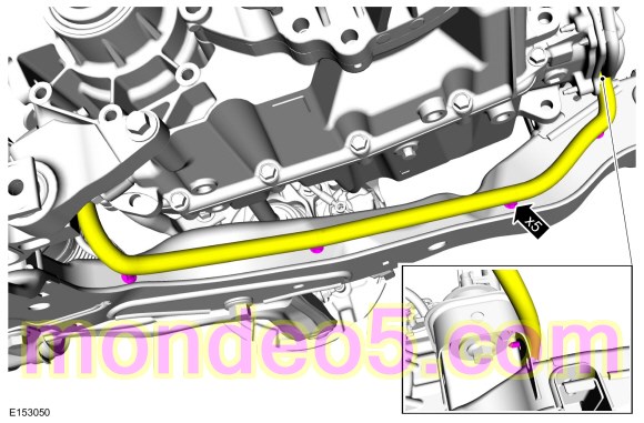
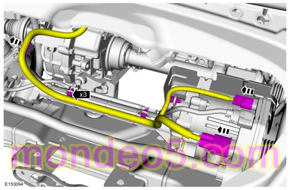
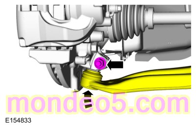
NOTE: The stabilizer bar links are designed with low friction ball joints that have a low breakaway torque.
NOTE: Use the hex-holding feature to prevent the ball stud from turning while removing or installing the stabilizer bar link nut.
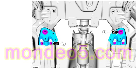
On both sides. Discard the specified component. Follow local disposal regulations.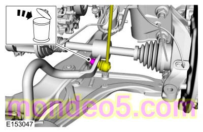
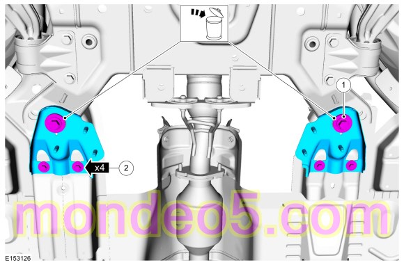
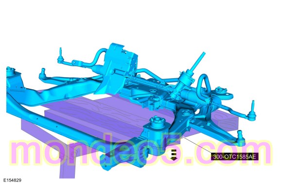
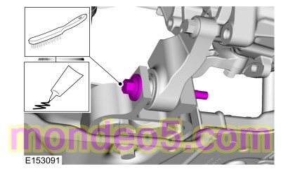
NOTICE: Do not use a prying device or separator fork between the ball joint and the wheel knuckle. Damage to the ball joint or ball joint seal may result. Only use the pry bar by inserting it into the lower arm body opening.
NOTICE: Use care when releasing the lower arm and wheel knuckle into the resting position or damage to the ball joint seal may occur.
On both sides. Discard the specified component. Follow local disposal regulations.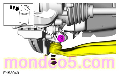


Installation

NOTE: Align reference marks made during removal.
Finger tight at this stage.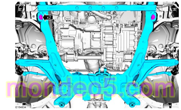
NOTE: While tightening the subframe bolts, make sure the front subframe does not move.
Torque : 235 NmNOTE: While tightening the subframe bolts, make sure the front subframe does not move.
Torque :
NOTE: The stabilizer bar links are designed with low friction ball joints that have a low breakaway torque.
NOTE: Use the hex-holding feature to prevent the ball stud from turning while removing or installing the stabilizer bar link nut.
On both sides.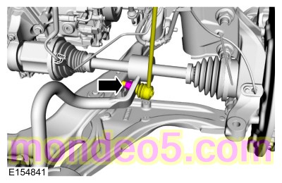
WARNING:
Do not reuse steering column shaft bolts. This may result in fastener failure and steering column shaft detachment or loss
of steering control. Failure to follow this instruction may result in serious injury to vehicle occupant(s).
Copyright © Ford Motor Company